|
With the standard installation of WR-G35DDCi/CR receivers in coherent mode, all of the WR-G35DDCi/CR receivers are required to be installed inside the same computer. However it is possible for multiple WR-G35DDCi/CR receivers to be installed into separate dedicated computers and still be operated in coherent mode by using the Extended Topology Configuration (ETC). Installation of the receivers using multiple computers allows for implementation of advanced parallel computing algorithms for phase-coherent systems.
To operate in the ETC configuration, each WR-G35DDCi receiver has to be equipped with the WR-ETC-100 'WiNRADiO Extended Topology Configuration Kit' (ETC Kit). The WiNRADiO 'WR-CC1PPS-100 Coherence Clock Kit' is also required. A detailed description of the ETC Kit and ETC mode of operation can be found in the WR-G35DDCi Multichannel Coherent Application Guide for Extended topology configuration(ETC).
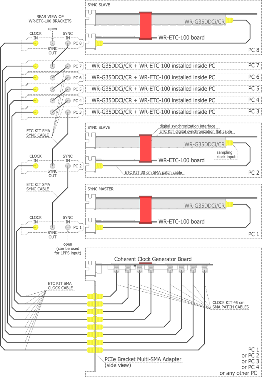
The ETC Kit consists of a single ETC board (a PCIe card), two long SMA coaxial cables, one flat cable and other kit accessories. One coaxial cable is for distribution of the 100 MHz coherent sampling clock. The second coaxial cable is for digital synchronization of the receivers. The flat cable connects the WR-G35DDCi/CR receiver with the ETC board. Each WR-G35DDCi receiver has to be equipped with the ETC kit, therefore the number of ETC kits required is equal to the number of WR-G35DDCi receivers in the coherent multichannel group.
The ETC Kit allows for implementation of larger distributed parallel computing multi-channel systems consisting of up to sixteen coherent receiving channels. Even larger configurations are possible as well. This introduces the possibility to implement advanced algorithms, such as the parallel multi-frequency and / or super-resolution estimation of direction of arrival (DoA, DF), multi-frequency beam-forming and other applications requiring coherent reception of radio signals and their computation intensive processing.
Please refer to G35DDC coherent mode SDK for ETC software support.
|